


Brain Shift Modeling for Epilepsy Surgery

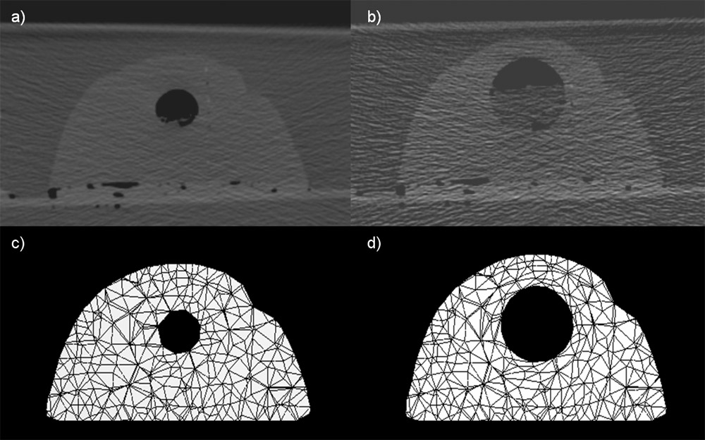
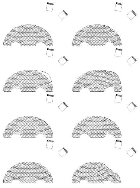
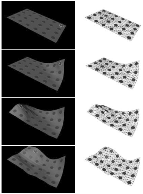
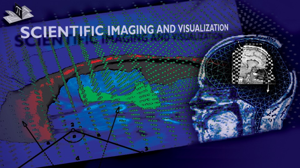
Surgical navigation systems are used intraoperatively to help the surgeon to ascertain her or his position and to guide tools within the patient frame with respect to registered structures of interest in the preoperative images. However, these systems are subject to inaccuracy caused by intraoperative brain movement (brain shift) since they assume that the inner head structures are rigid. Experiments show brain shifts of up to several millimeters, making it the cause of the dominant error in those systems. We have proposed an approach for reducing this error based on a deformable brain model [1,2,3]. Here we present three such brain models: a 2D spring-dashpot-mass model, a 3D spring-dashpot-mass, and a 3D finite element method (FEM) model. The initial model geometry is obtained from pre-operative images, as shown in Fig. 1 for the 2D model. The brain tissue is modeled as a homogeneous linear visco-elastic material, although the model allows for setting the tissue properties locally. Gravity draws the brain downwards which in turn interacts with the skull and other surrounding structures. A time-course of the brain 2D model deformation is shown in Fig. 2.
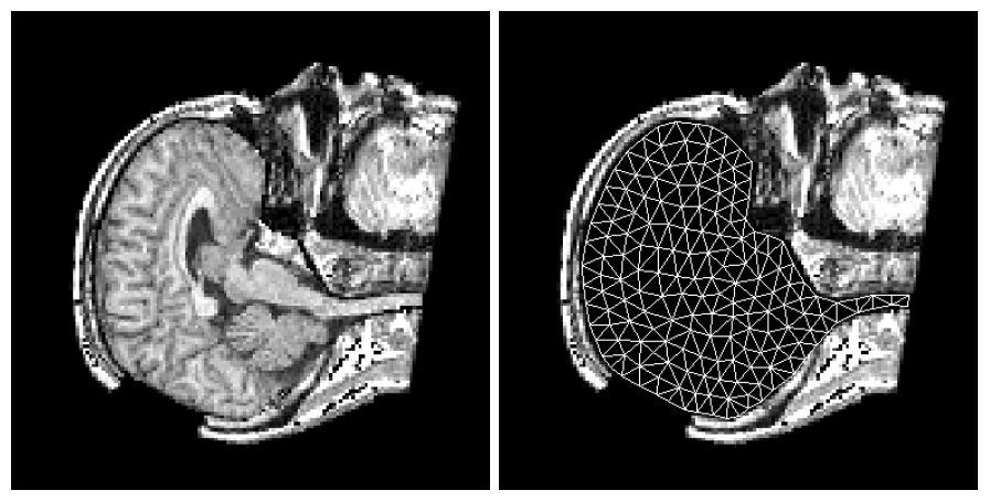
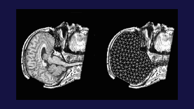
Figure 1: The initial model mesh was set over the segmented brain, while the craniotomy was simulated by removing a part of the skull from the image. The figure is from [1] and it is used with permission; Copyright © 1998 Springer Berlin / Heidelberg; All rights reserved.
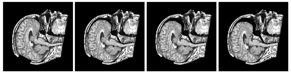
Figure 2: A time sequence showing the brain model deformation. From left to right are the initial state, two intermediate states after equal intervals and the final (rest) state. As the brain model settled down due to gravity, there were not only posterior movements, but also slight extensions in superior and inferior directions. The figure is from [1] and it is used with permission; Copyright © 1998 Springer Berlin / Heidelberg; All rights reserved.
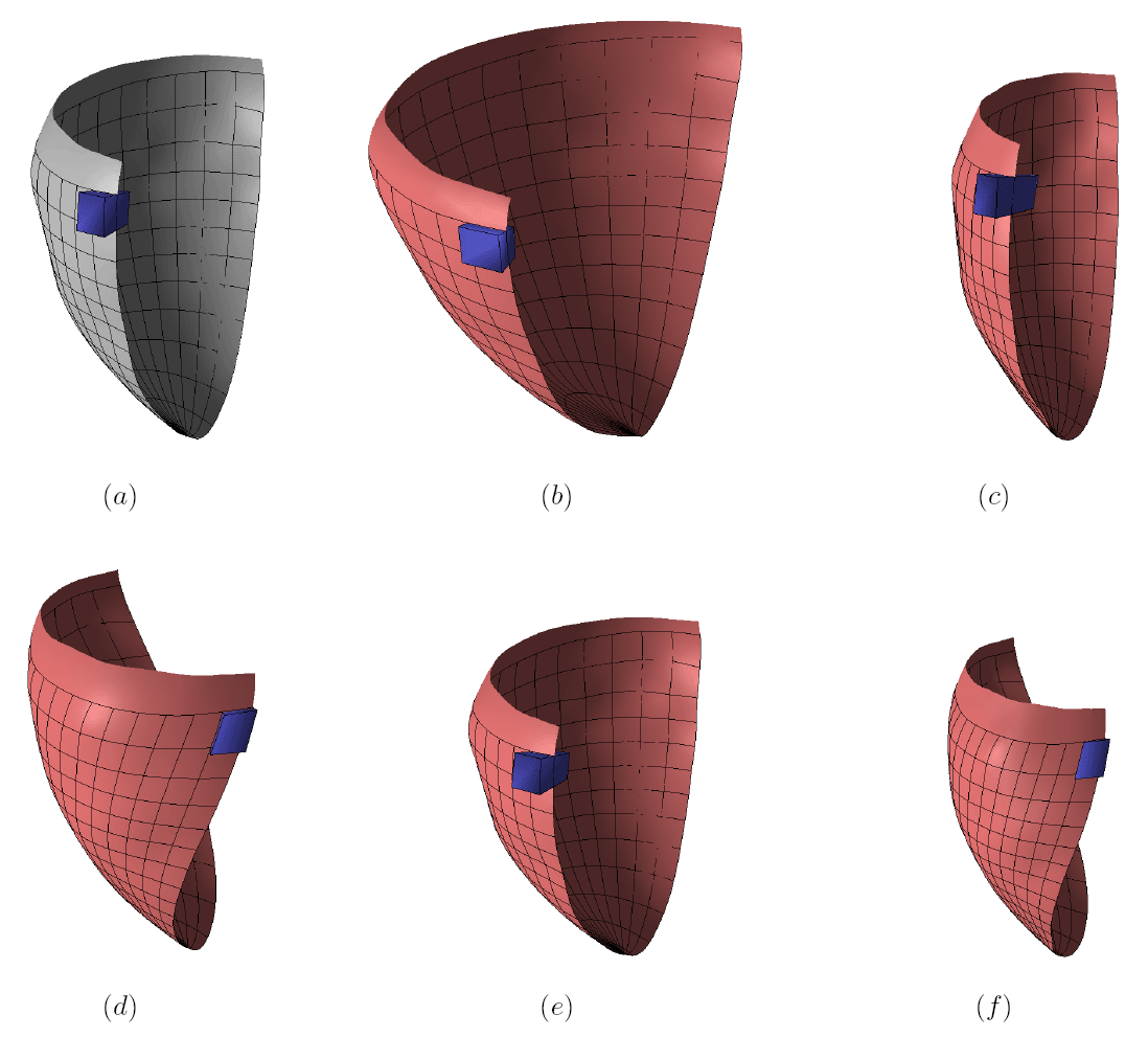
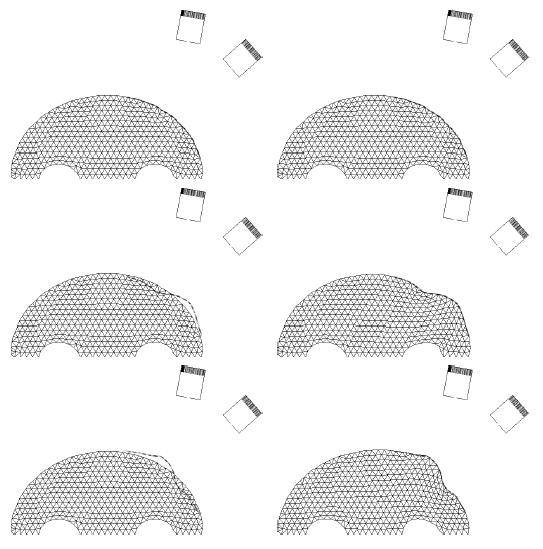
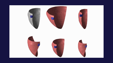
By varying the model parameters one can control the model behavior. While model parameters can be controlled locally, Figs. 3 and 4 demonstrate the brain 2D model deformation when the model stiffness is changed globally.
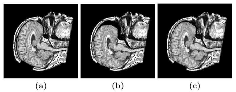
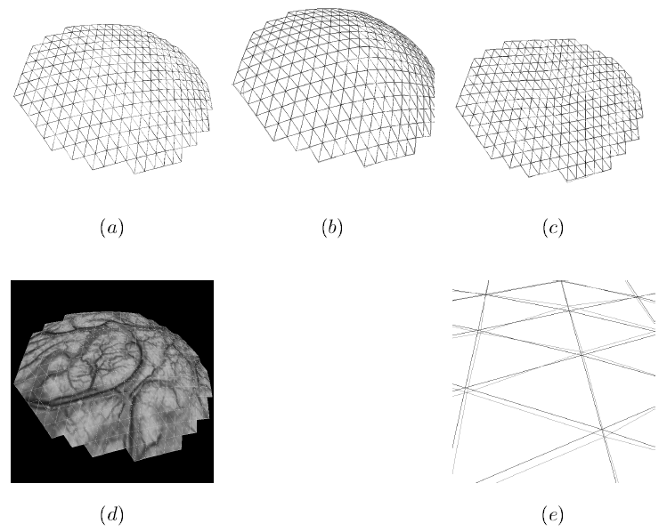
Figure 3: Model deformation comparison for different tissue properties. (a) Initial state, (b) final (rest) state for a "softer" case, (c) final (rest) state for a "stiffer" case. Note the difference in the curvature of the brain boundary at the position of the skull opening for the two cases. The largest deformation is at the anterior part of the brain. The figure is from [1] and it is used with permission; Copyright © 1998 Springer Berlin / Heidelberg; All rights reserved.
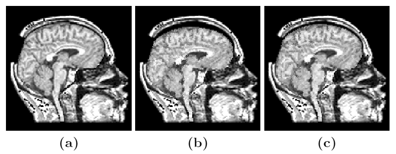
Figure 4: Model deformation comparison for different tissue properties (another angle). (a) Initial state, (b) final (rest) state for a "softer" case, (c) final (rest) state for a "stiffer" case. Note the deformation at the top of the superior part of the brain. The figure is from [1] and it is used with permission; Copyright © 1998 Springer Berlin / Heidelberg; All rights reserved.
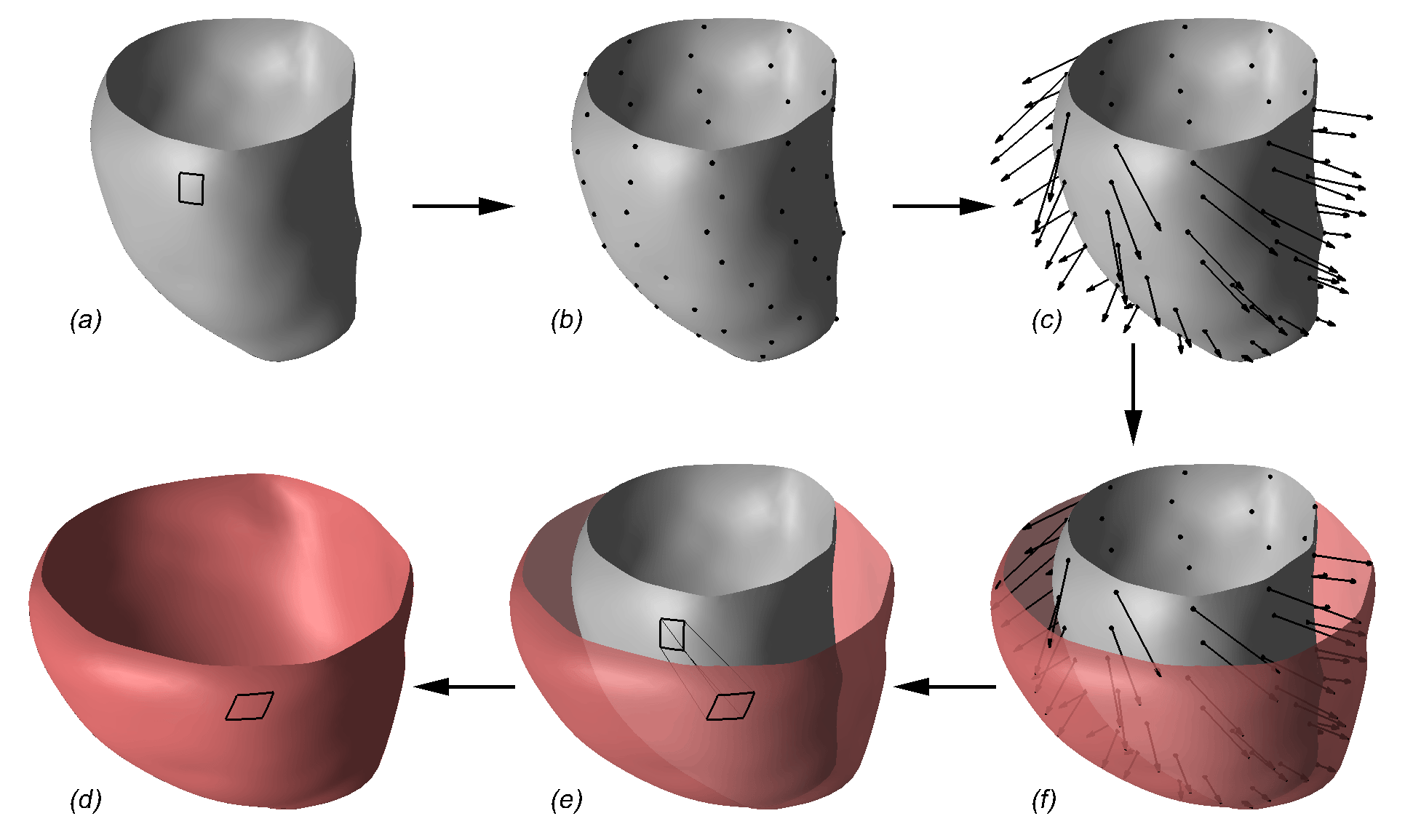
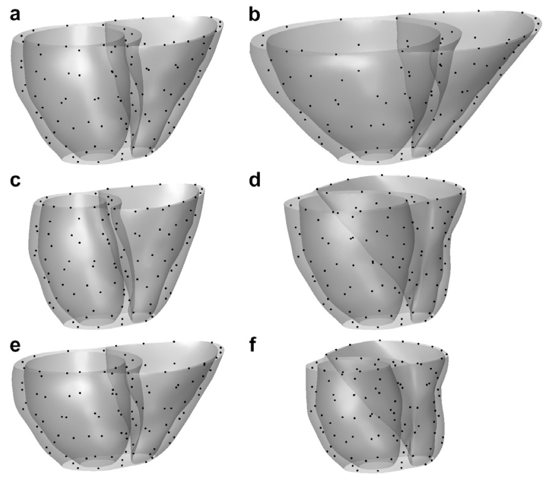
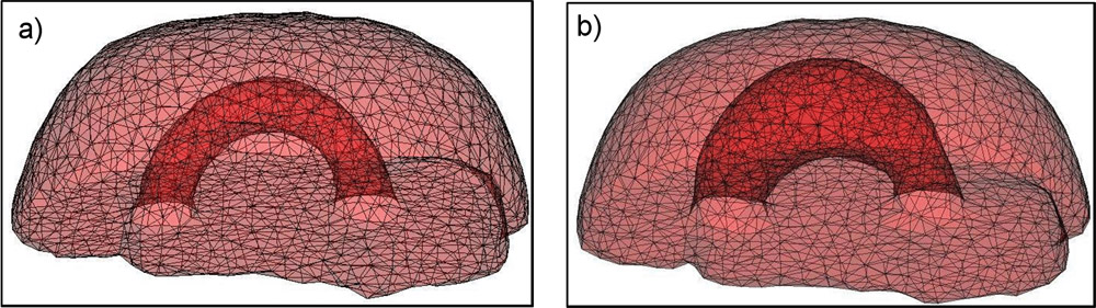
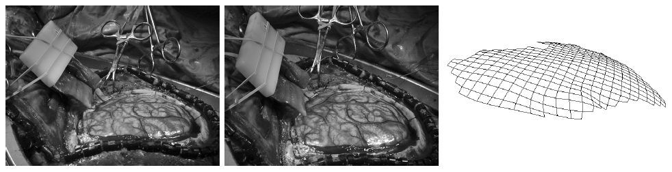
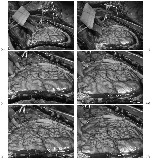
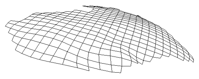
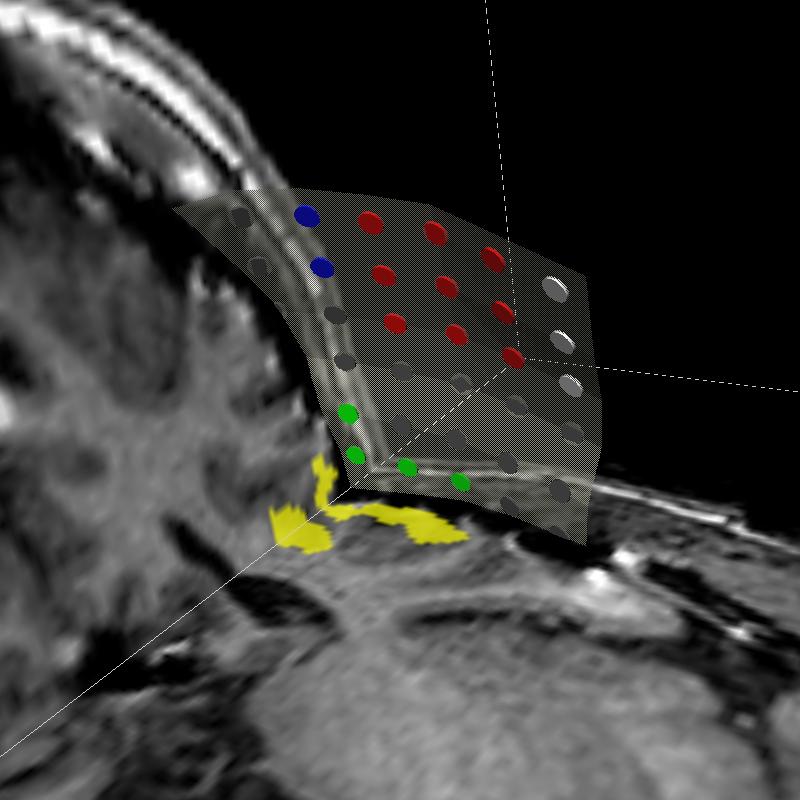
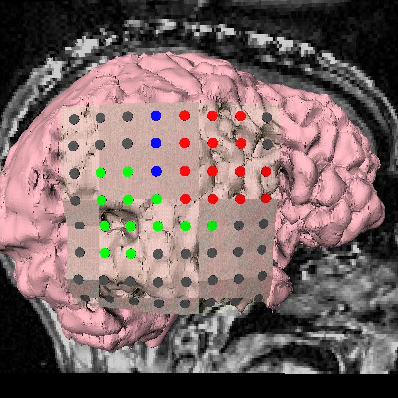
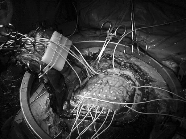
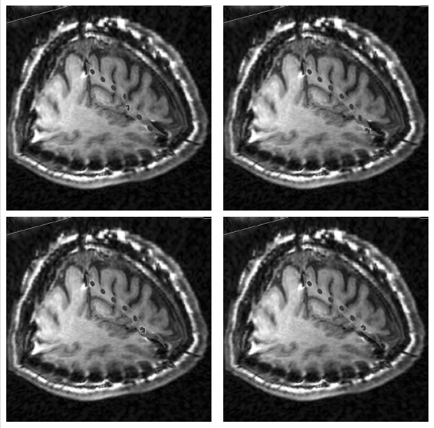
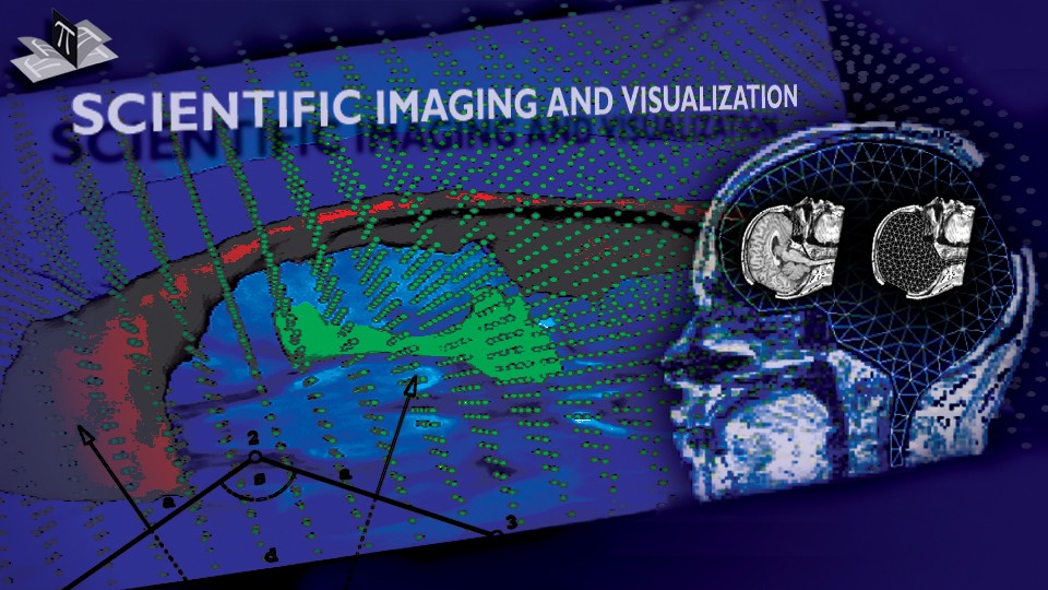
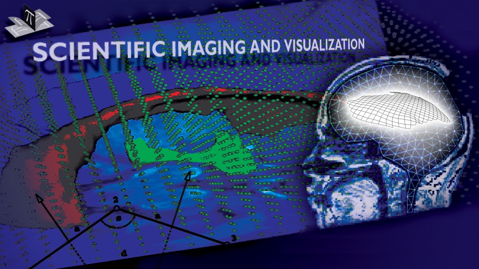
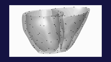
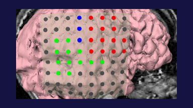
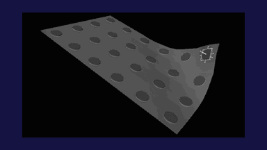
The 3D spring-dashpot-mass brain model, whose mesh is shown in Fig. 5, exhibits similar behavior as its 2D counterpart. To guide and validate the model we intraoperatively recorded the locations of several points on the exposed brain surface over the course of the surgery of an epilepsy patient. The intraoperatively recorded points are shown in Fig. 6, while Fig. 7 shows the point-guided brain model deformation.
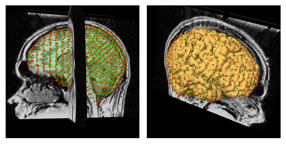
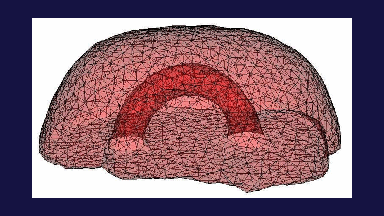
Figure 5: 3D Brain Model Mesh. The left figure shows the mesh, while the right one shows the mesh and the outer brain surface. The mesh has over 2000 nodes and 1500 elements (bricks). The figure is from [2] and it is used with permission; Copyright © 2002 Oskar Skrinjar; All rights reserved.
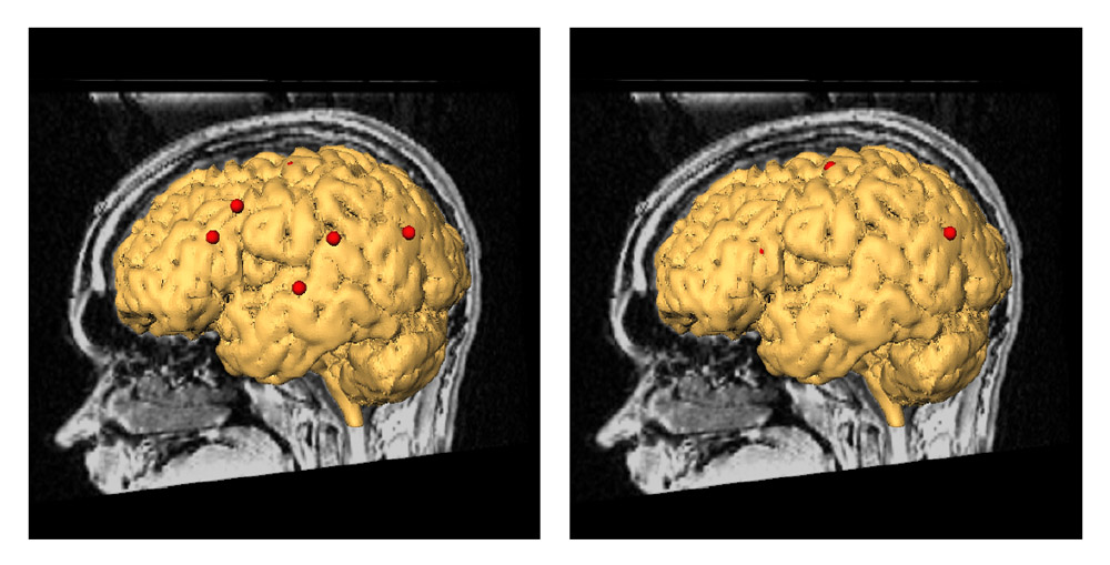
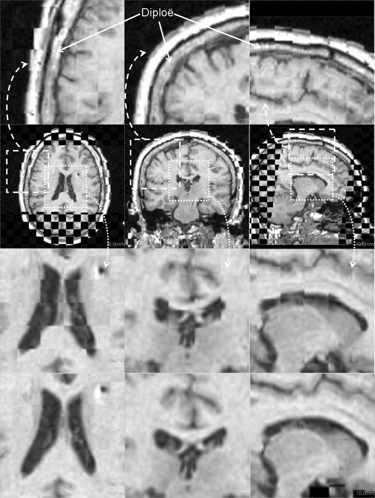
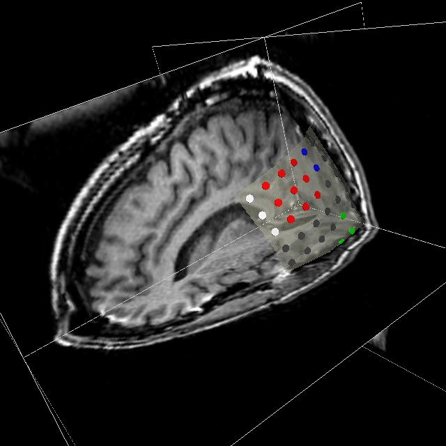
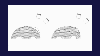
Figure 6: Intraoperatively Recorded Points on the Exposed Brain Surface. Intraoperatively recorded points on the exposed brain surface at the beginning of the surgery are shown at left, while their position about 45 minutes later relative to the same pre-deformation brain surface are shown at right. The points moved in the direction of gravity (which is perpendicular to the sagittal plane) for a few millimeters and they are hidden under the pre-deformation brain surface (only one of the points is still visible in the figure at right). Since the brain deformed (in the direction of the gravity vector), the surface points moved relative to the pre-deformation brain surface. The figure is from [2] and it is used with permission; Copyright © 2002 Oskar Skrinjar; All rights reserved.
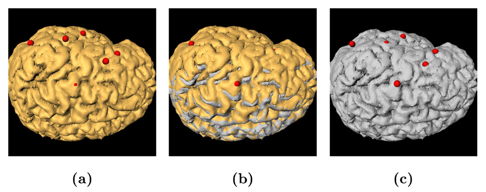
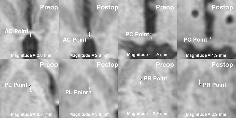
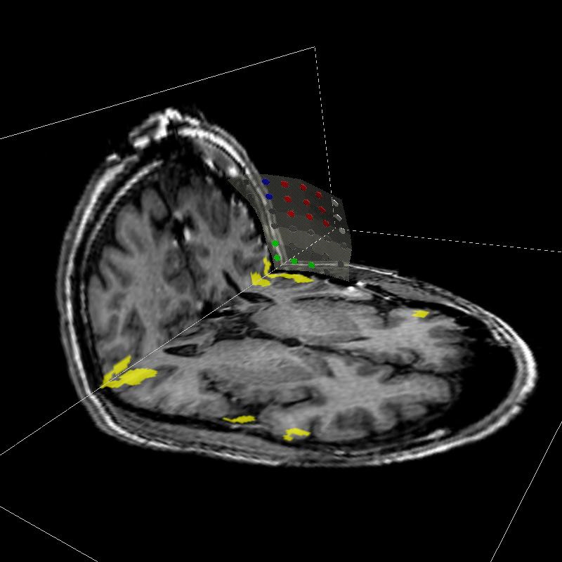
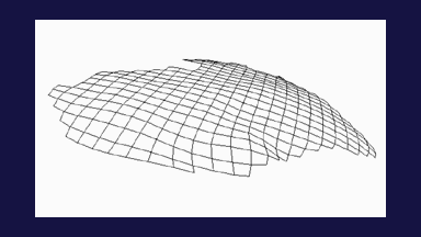
Figure 7: An Example of a Guided Brain Model Output. (a) shows the recorded points at the beginning of the surgery with the initial (pre-deformation) brain surface. Note that the points are on the brain surface. (b) represents the final (steady-state) brain surface points with the initial brain surface (yellow surface) and the final brain surface (gray surface). One can see that the brain surface points moved inside the initial brain surface. This is due to the effect of gravity that pulled the brain downwards. (c) represents the final brain surface points and the final brain surface after model-guided updating. The points are again on the brain surface. The final brain model surface was computed using the final model state, while the final points are the measurements on the brain surface when the brain settled down. The figure is from [2] and it is used with permission; Copyright © 2002 Oskar Skrinjar; All rights reserved.
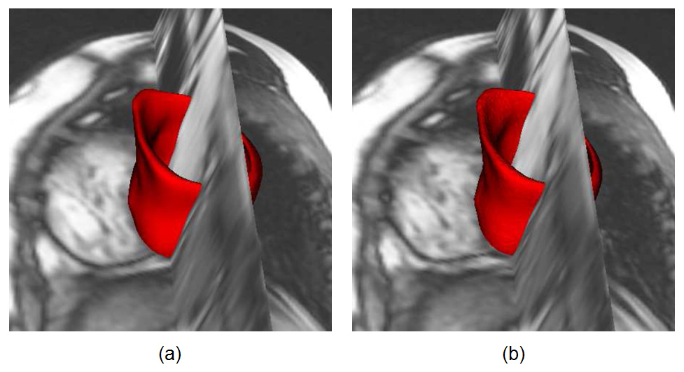
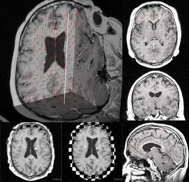
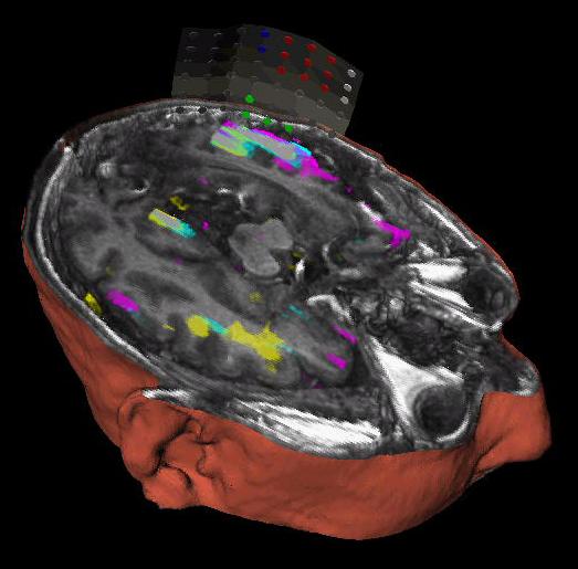
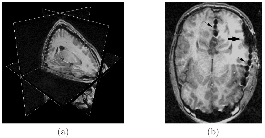
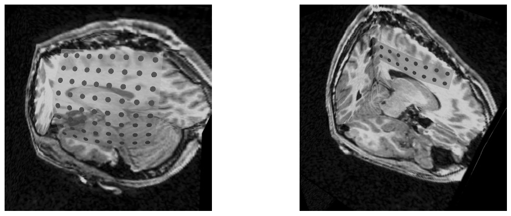
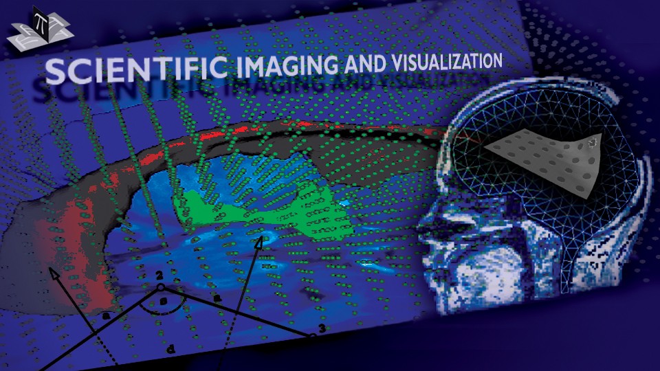
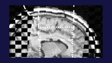
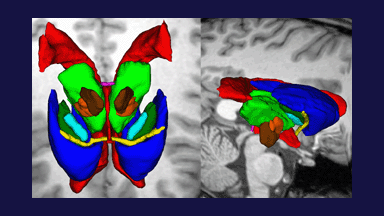
The result of applying the 3D FEM model to pre-operative MRI images of two patients is shown in Fig. 8 along with the corresponding intraoperative MRI. One can see that the model-updated pre-operative MRI and intraoperative MRI are relatively similar. This example, as well as the above examples with 2D and 3D spring-dashpot-mass models, suggest that deformable brain models have the capacity to compensate for a part of the intraoperative brain deformation.
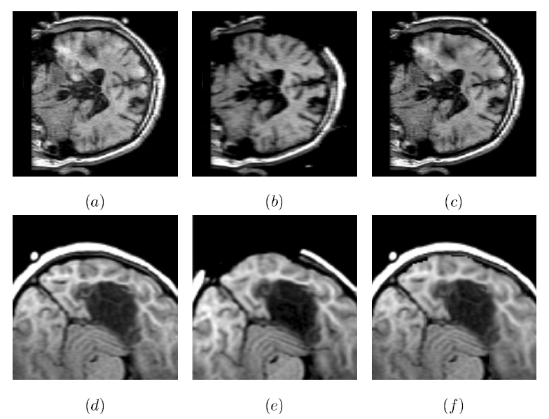
Figure 8: Model-Updated Preoperative MR Brain Images. (a) A preoperative coronal slice of a sinking brain, (b) the corresponding intraoperative slice of the deformed brain, (c) the corresponding model-computed slice of the deformed brain. Axial slices (d), (e) and (f) correspond to the bulging brain case (undeformed, deformed, and model-computed, respectively). Note that in both cases the exposed brain surface in the computed slice moved similarly as the corresponding surface in the intraoperative slice. The figure is from [2] and it is used with permission; Copyright © 2002 Oskar Skrinjar; All rights reserved.
References:
[1] Skrinjar, O., Spencer, D., Duncan, J., "Brain Shift Modeling for Use in Neurosurgery", Medical Image Computing and Computer Assisted Intervention, Proceedings, Boston, MA, USA, pp. 641-649, October 1998. LINK
[2] Skrinjar, O., "Deformable Models in Image-Guided Neurosurgery", PhD Thesis, Yale University, May 2002. LINK
[3] Skrinjar, O., Duncan, J., "Model-Driven Brain Shift Compensation", Medical Image Analysis, 6(4): 361-373, December 2002. LINK