


Brain Shift Analysis for Deep Brain Stimulation Surgery

Deep brain stimulation (DBS) surgery can significantly improve the quality of life for patients suffering from movement disorders, but the success of the procedure depends on the implantation accuracy of the DBS electrode array. Pre-operative surgical planning and navigation are based on the assumption that the brain tissue is rigid between the time of the acquisition of the pre-operative image set and the time of surgery. A shift of deep brain structures by only a few millimeters can potentially increase the number of required microelectrode and/or macroelectrode tracks and decrease implantation accuracy. We studied 25 subjects that underwent DBS surgery and analyzed brain shift between pre-operative and post-operative 3D MRI scans using a 3D non-rigid registration algorithm. The registration algorithm automatically aligned the pre-operative and the post-operative 3D MRI scans and provided the shift vectors over the entire brain. The images were first aligned rigidly and then non-rigidly registered with an algorithm based on thin plate splines and maximization of the normalized mutual information. Steps of the registration algorithm are shown in Fig. 1, while the brain shift vector field of one of the subjects is shown in Fig. 2.
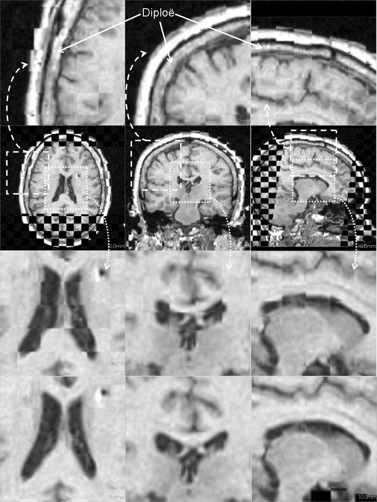
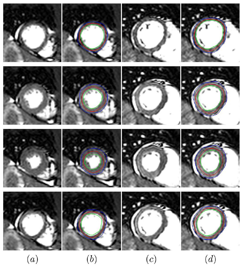
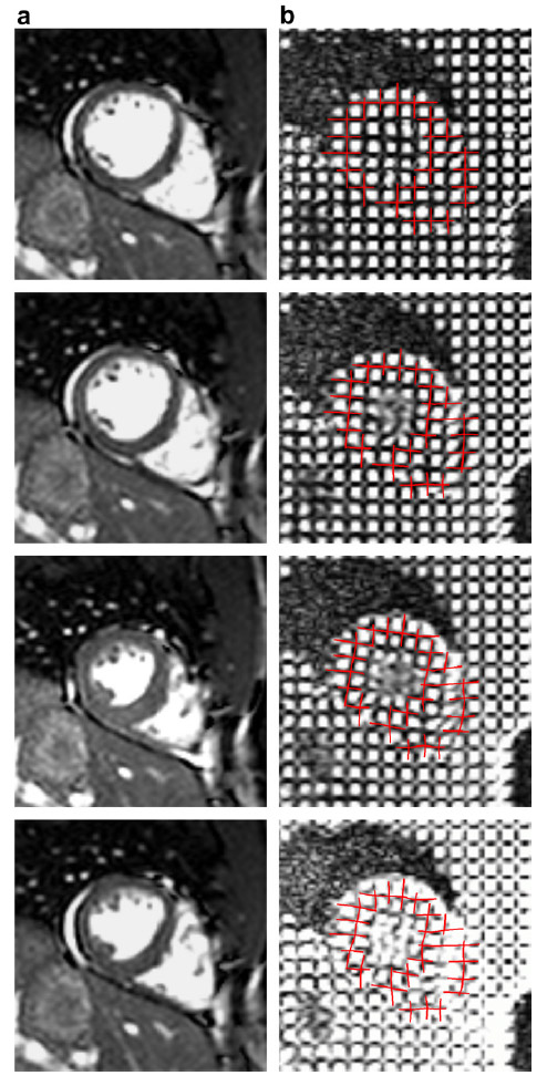
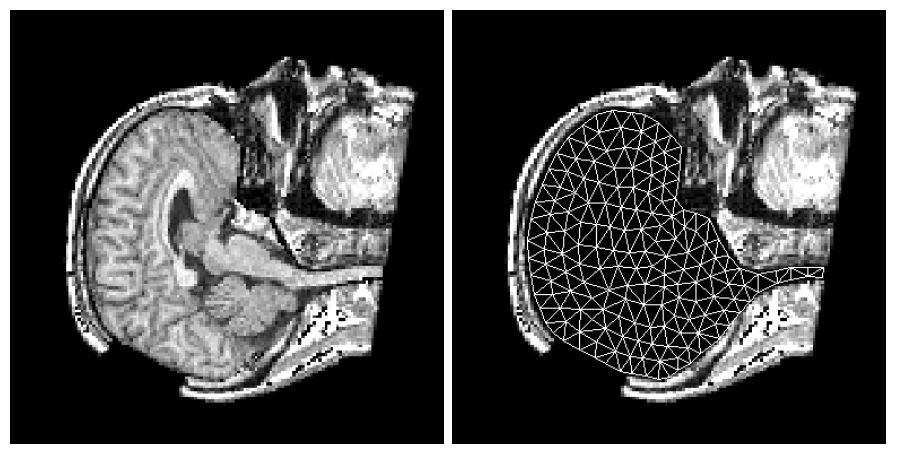
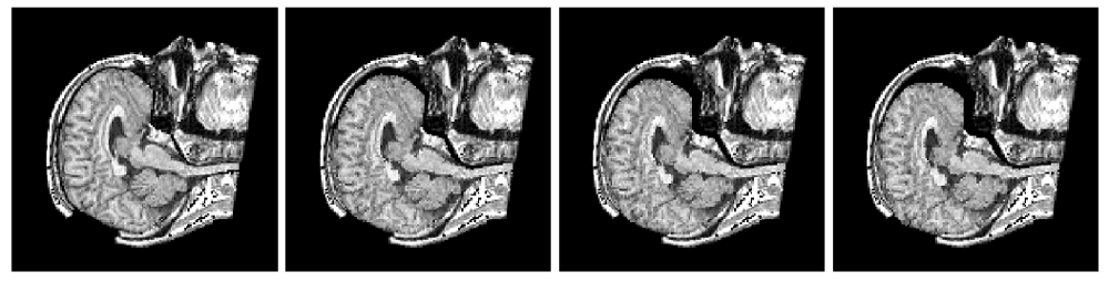
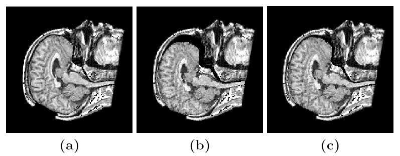
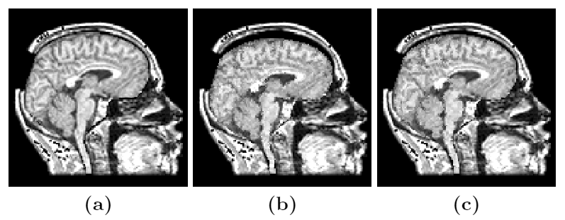
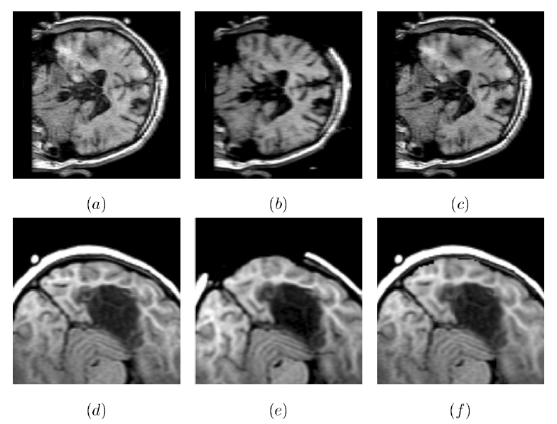
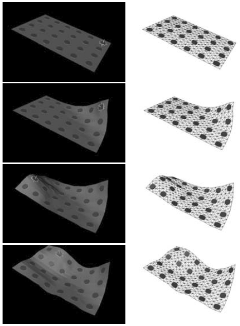
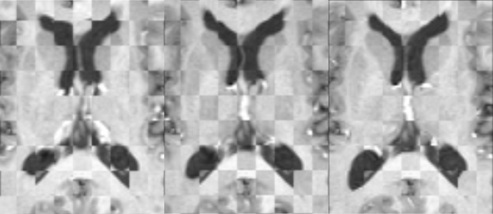
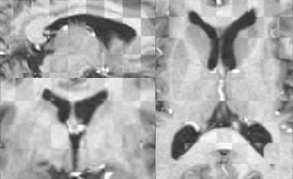
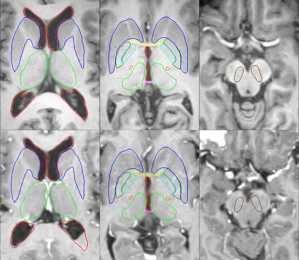
Figure 1: The result of the two-stage registration process for one of the subjects is shown in axial (first column), coronal (second column), and sagittal (third column) views. The second row shows the full slices of the rigidly aligned pre-op and post-op images, while the first row shows the corresponding zoomed-in skull regions and the third row shows the corresponding zoomed-in ventricular regions, all after the rigid registration. The fourth row shows the same ventricular regions after the non-rigid registration. All the views contain checkerboard displays of the pre-op image and the registered post-op image. Note the good alignment of the diploe in the top row, which suggests that the rigid registration was accurate. The misalignment of the outer edge of the skin in the pre-op and the post-op image in the top row was likely caused by the deformation of the soft tissues outside the skull. The misaligned ventricles in the third row show that the soft structures deformed between the two scans, while the well aligned ventricles in the fourth row suggest that the non-rigid registration was accurate. The figure is from [1] and it is used with permission; Copyright © 2007 S. Karger AG, Basel. All rights reserved.
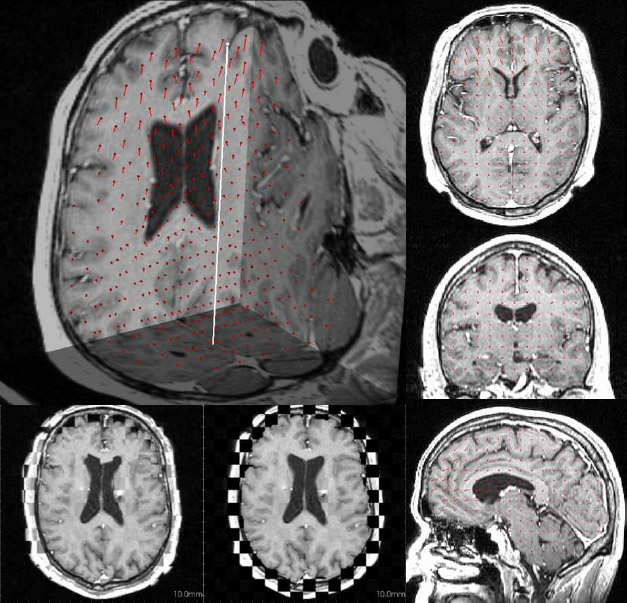
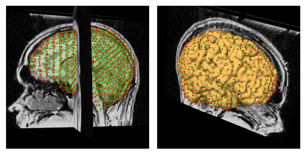
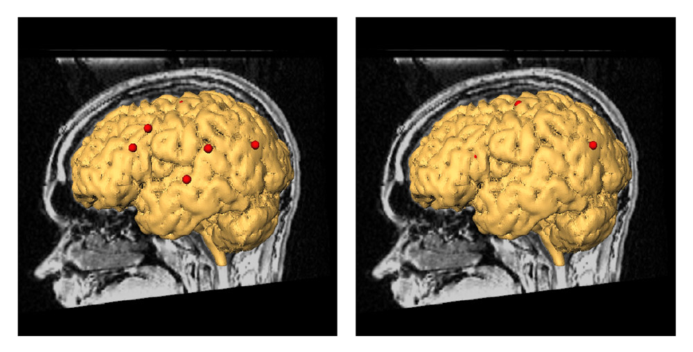
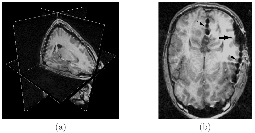
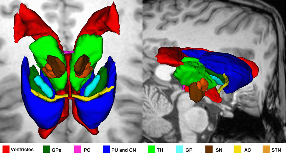
Figure 2: Vector field plot of brain shift vectors for one of the subjects shown on 3D pre-op image (top left image). Three images in the right column are axial, coronal and sagittal slices with the projections of the 3D shift vectors to the 2D slice. The white vector is the direction of gravity and red vectors are the shift vectors. Red dots in the 2D slices and red spheres in the 3D image represent the base of the shift vectors, whereas the lines show their length and direction. The bottom left image is the checkerboard image of the pre-op and the diploe-based rigidly registered post-op image whereas the bottom center image is the checkerboard image of the pre-op and the non-rigidly registered post-op image. The figure is from [2] and it is used with permission; Copyright © 2007 Society of Photo-Optical Instrumentation Engineers (SPIE). All rights reserved.
Brain shift of up to 4 mm was observed in deep brain structures. Fig. 3. shows the brain shift vectors at the anterior commissure (AC), the anterior edge of the posterior commissure (PC), the medial-anterior corner of left putamen (PL) and the medial-anterior corner of right putamen (PR) for one of the subjects. On average, the recorded shift was in the direction of gravity, with deeper structures experiencing smaller shift than more superficial structures. The main conclusion of the study is that the brain shift is comparable to the size of the targets in deep brain stimulation surgery and should not be ignored. Techniques that minimize the amount of brain shift may therefore lead to increased accuracy of DBS lead implantation.
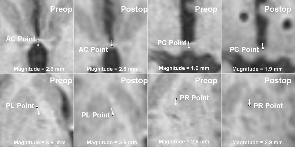
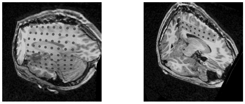
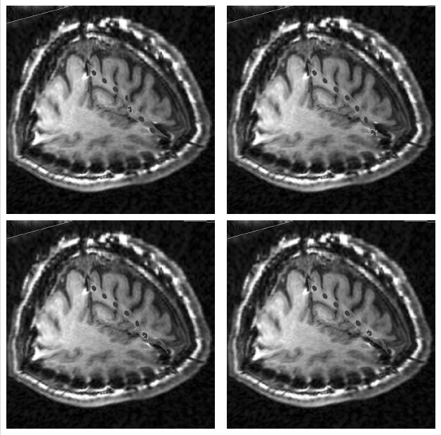
Figure 3: Brain shift vectors of AC, PC, PL and PR points (marked as white points) superimposed on the axial slices of the pre-op and the rigidly registered post-op image of a subject. The magnitude and projection to the axial plane of each brain shift vector are shown in the pre-op image and in the corresponding position in the post-op image. The figure is from [1] and it is used with permission; Copyright © 2007 S. Karger AG, Basel. All rights reserved.
References:
[1] Khan, M., Mewes, K., Gross, E. R., Skrinjar, O., "Assessment of Brain Shift Related to Deep Brain Stimulation Surgery", Stereotactic and Functional Neurosurgery, 86(1): 44-53, 2008. LINK
[2] Khan, M., Mewes, K., Gross, E. R., Skrinjar, O., "Brain Shift Analysis for Deep Brain Stimulation Surgery Using Non-Rigid Registration", SPIE Medical Imaging, San Diego, CA, USA, Vol. 6509, February 2007. LINK