


Subdural Electrode Extraction and Visualization

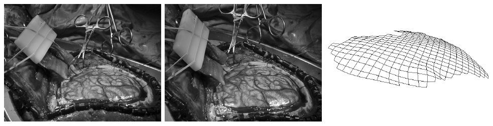
It is common in epilepsy surgery to implant grids and strips of electrodes between the skull and brain or inside the brain, in order to localize functional areas (Fig. 1). MR scans are currently used for a variety of image-guided surgical planning tasks, including the localization of the electrode grids. However, the MR scan taken of a patient with implanted electrodes is distorted, and it is difficult to visualize and relate the electrode positions to head and brain structures (Fig. 2).
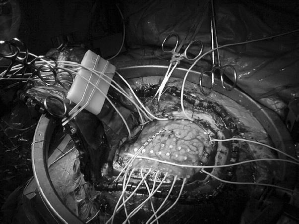
Figure 1: Electrode grid implantation. An 8 by 8 subdural grid of electrodes is placed on the exposed brain surface. The white wires coming out from the gap between the brain and the skull are from electrode strips that have already been implanted. The figure is from [1] and it is used with permission; Copyright © 2000 IEEE; All rights reserved.
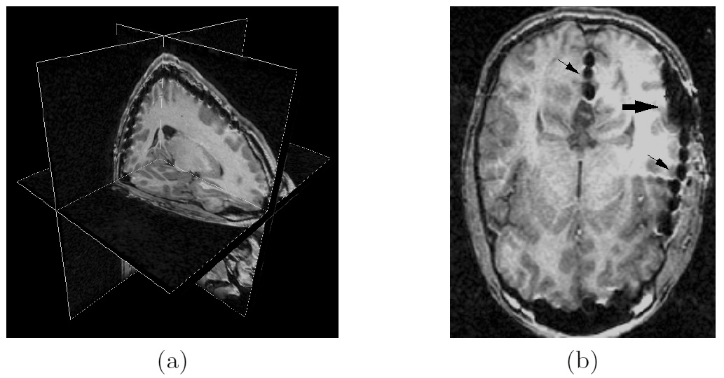
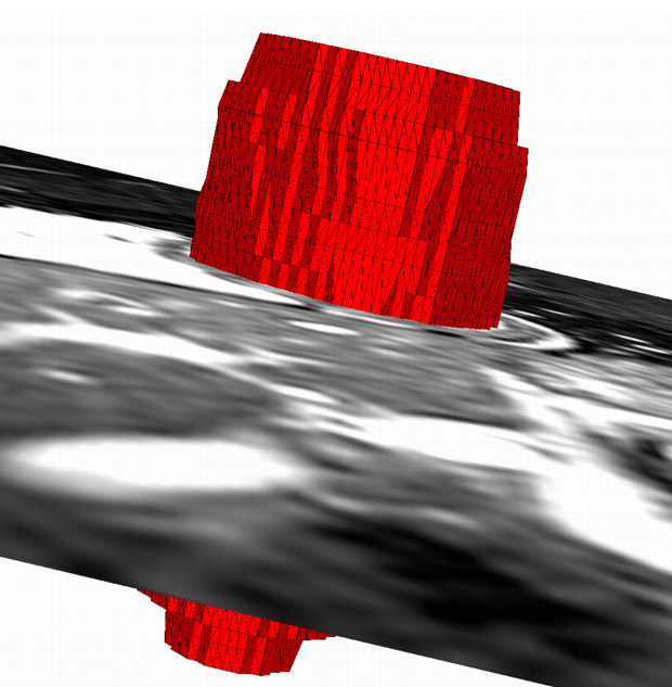
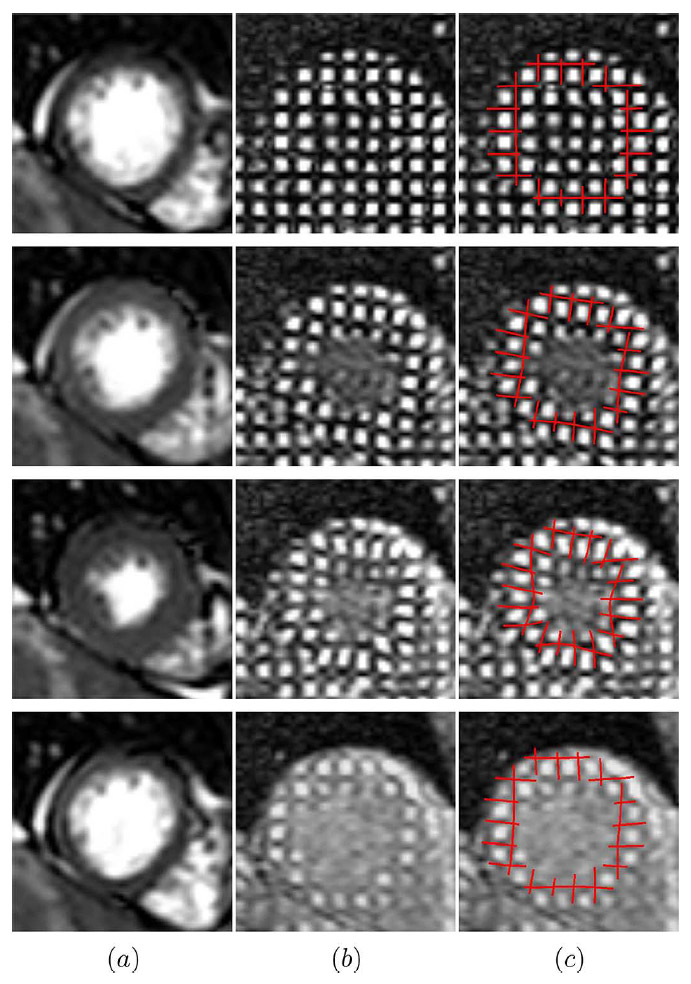
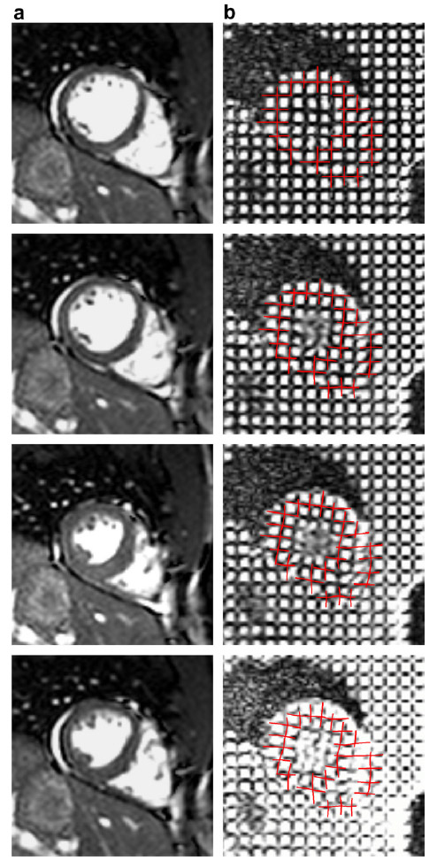
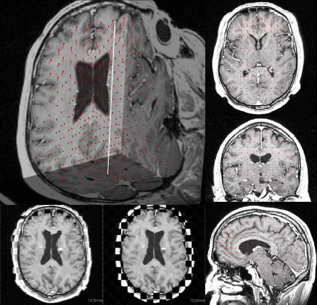
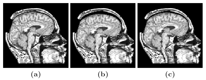
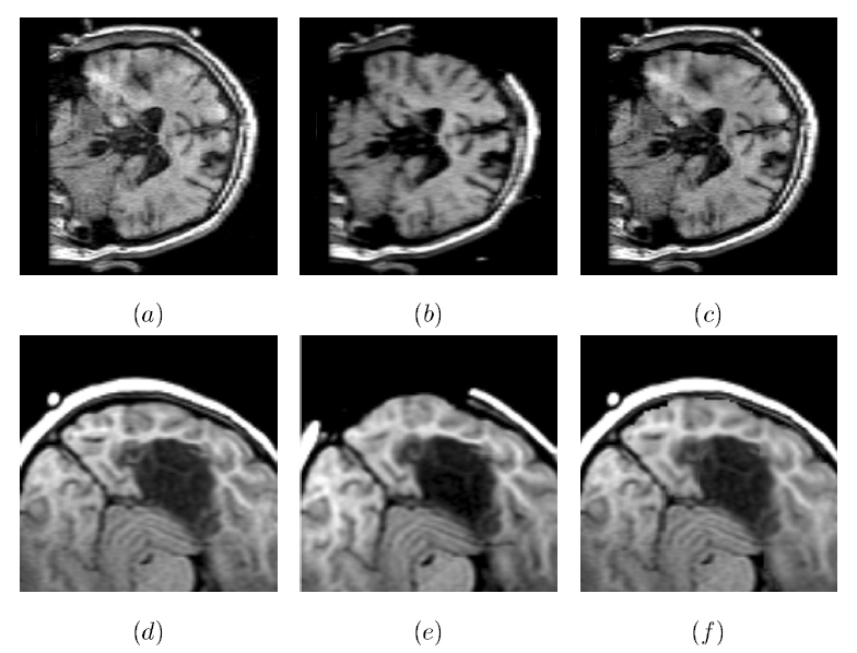
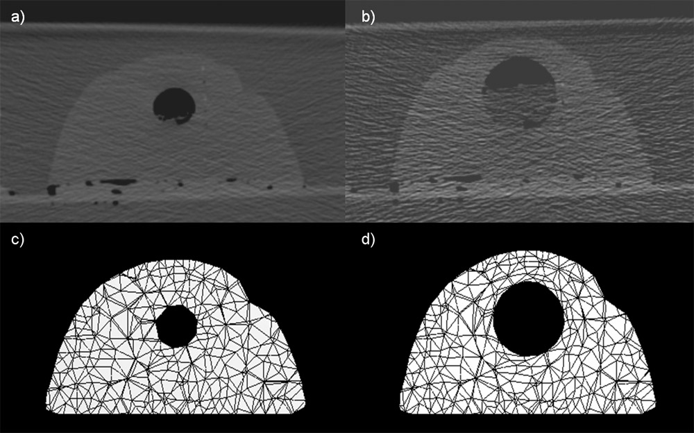
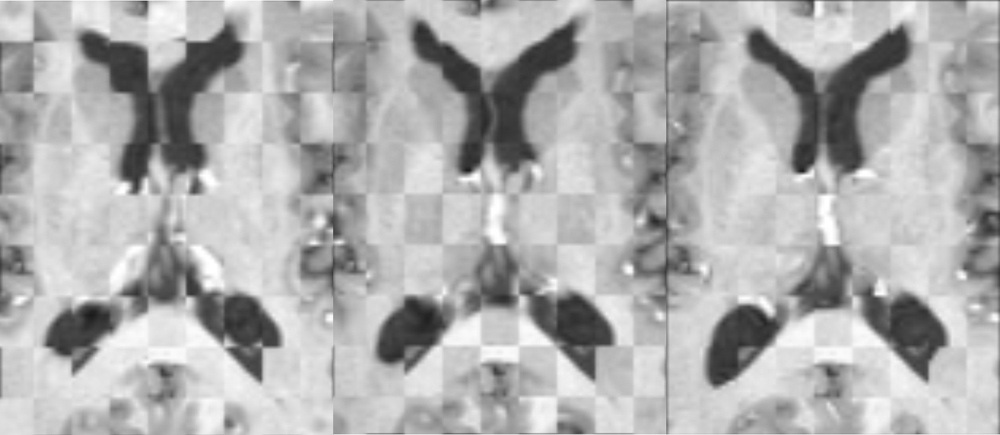
Figure 2: Figure (a) shows three orthogonal sections through a post-op MR scan. One can see the artifacts caused by electrodes of an 8 by 8 grid between the top of the brain and the skull. It is not easy to visualize where those electrodes are in the grid and how they are related to brain structures of interest. Figure (b) shows an axial slice of another patient. The artifacts are usually sphere-shaped (small arrows), but sometimes (big arrow) are so dominant that it is very difficult even for the human eye to locate the electrode positions. The figure is from [2] and it is used with permission; Copyright © 1999 Springer Berlin / Heidelberg; All rights reserved.
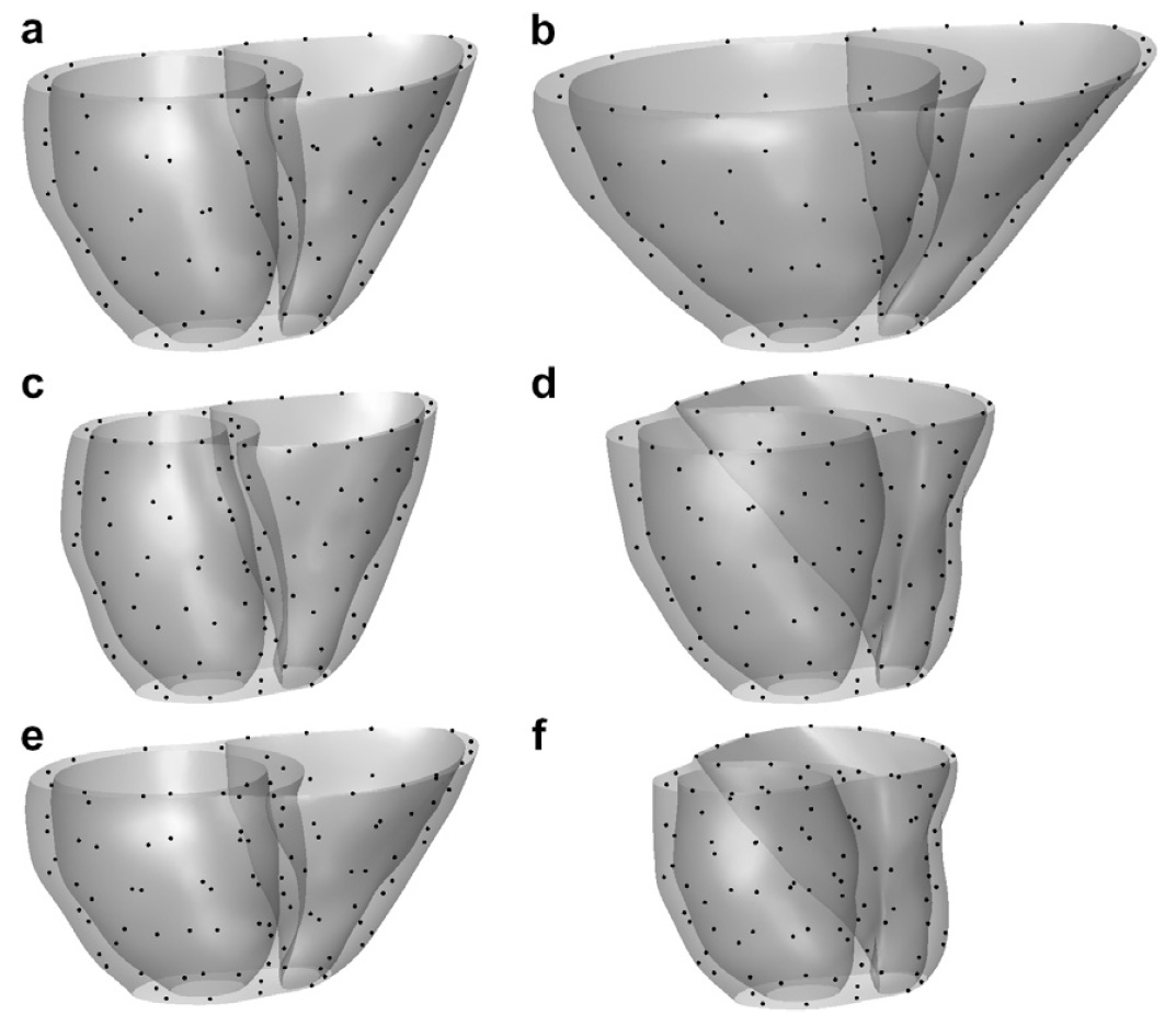
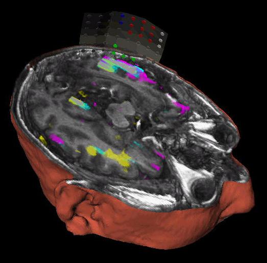
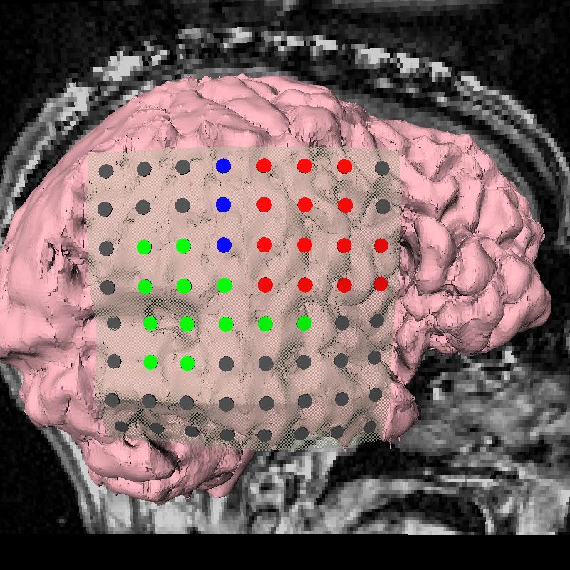
For this reason we have developed an automatic algorithm that reliably extracts grids of electrodes from corrupted post-op MR scans [2]. The grid is fitted as a smooth, curved surface through the estimated electrode positions, properly estimating the orientation of the thin disk-shaped electrodes. The extracted grid is then displayed in 3D together with the desired brain structures, color-coding the electrodes corresponding to particular functional areas. Examples of extracted electrode grids can be seen in Fig. 3 and at the Brain Multimodality Registration and Visualization project page.
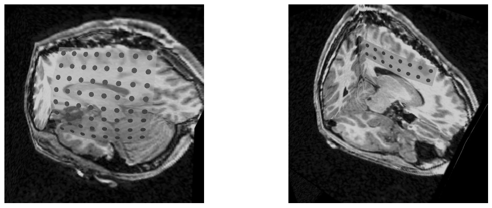
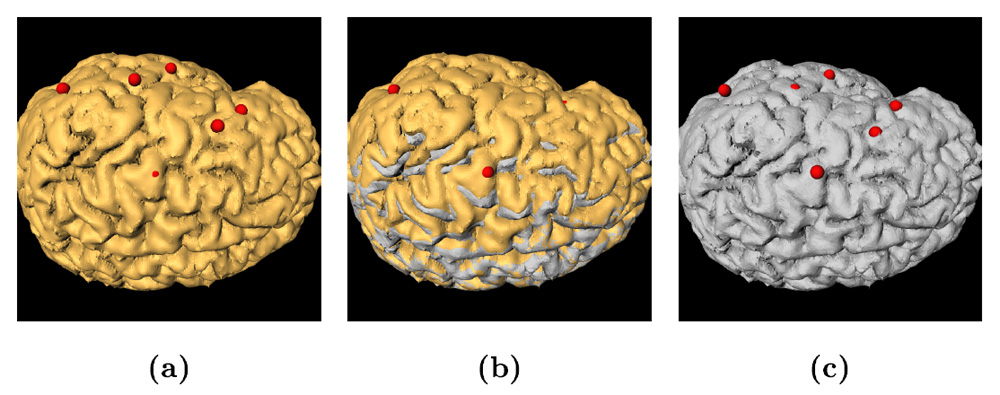
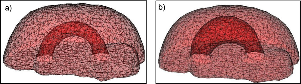
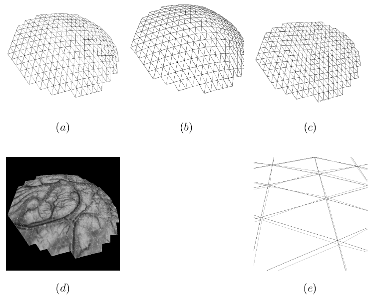
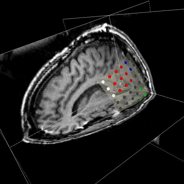
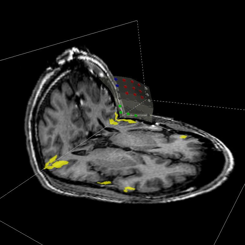
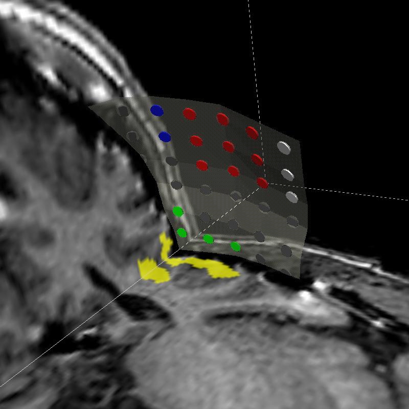
Figure 3: These two figures show examples of the final electrode grid, represented as a smooth surface with disk-shaped electrodes properly oriented. The electrodes can be color-coded to denote functional areas. The figure is from [2] and it is used with permission; Copyright © 1999 Springer Berlin / Heidelberg; All rights reserved.
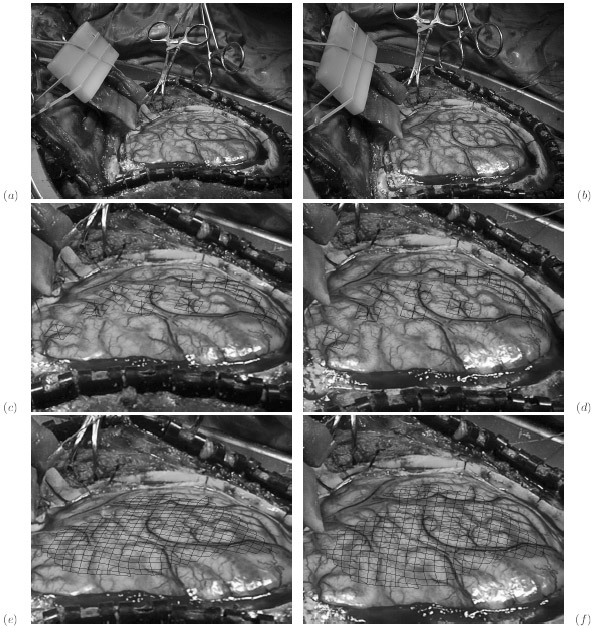
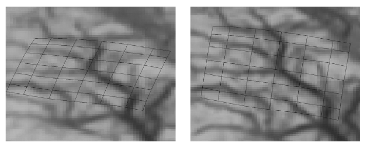
In addition to the automated subdural electrode extraction, we have developed methods for interactive manipulation of electrode grids, in case the automated results need to be corrected [1,3]. Figs. 4 and 5 illustrate the interactive manipulation. With these tools it is much easier to visualize and relate the position of the functional areas of interest with respect to brain anatomy and plan the surgery.
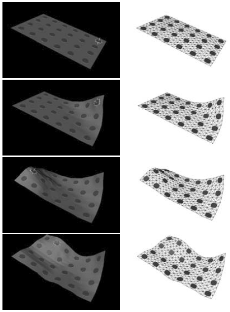
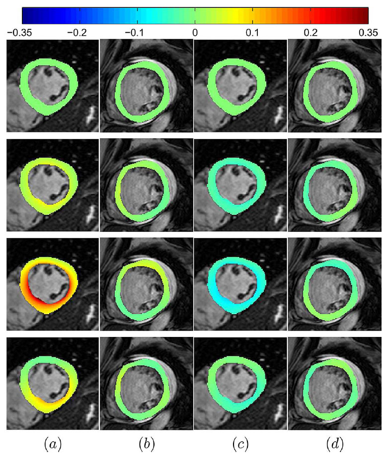
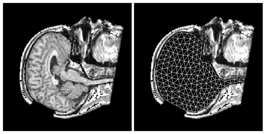
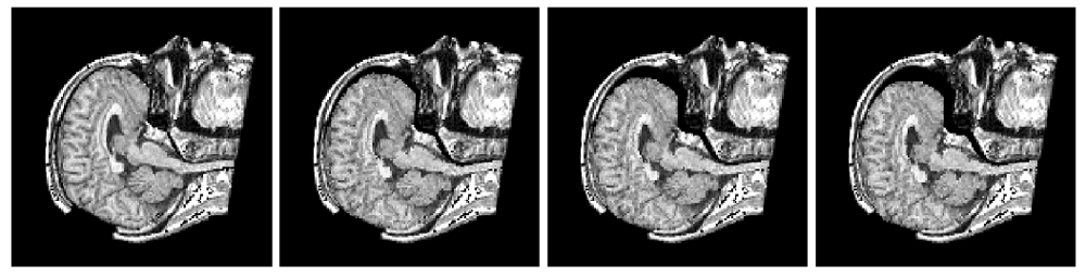
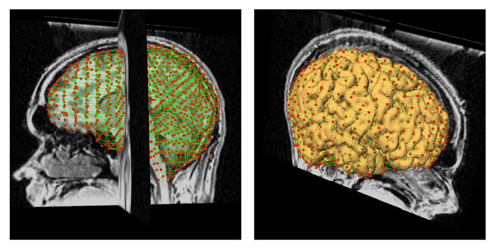
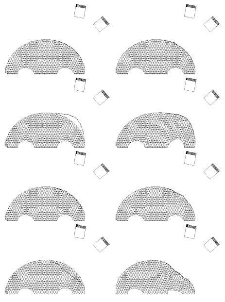
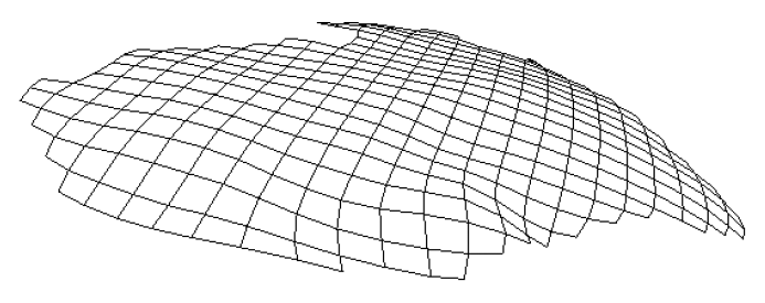
Figure 4: The left and right figures show a sequence of deformed electrode grid (a grid of 6 by 4 electrodes) and the corresponding underlying model, respectively. The model is composed of nodes interconnected with springs (the lines in the right figures) and it assures that the intrinsic surface distances are preserved within the specified relative error. In the left images one can see the selected electrode that is manipulated by the user. The user can move the selected electrode in the surface tangent plane or normal to it. The figure is from [1] and it is used with permission; Copyright © 2000 IEEE; All rights reserved.
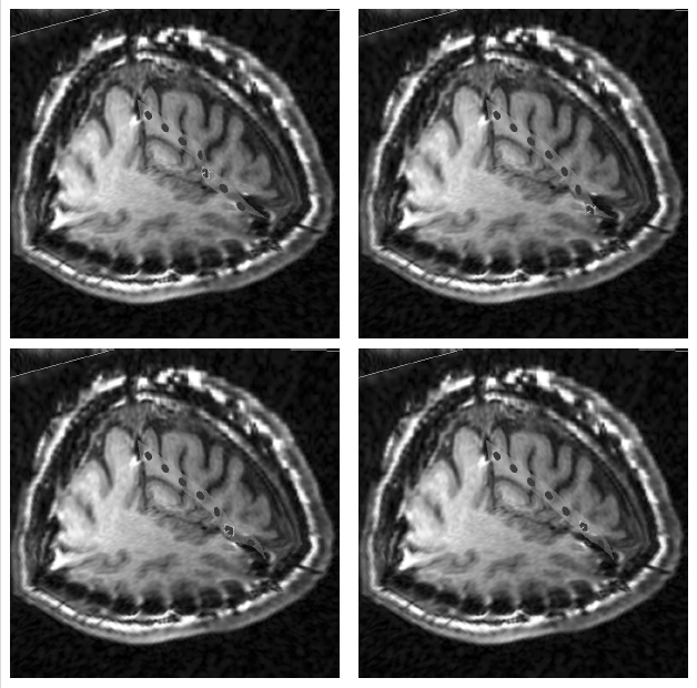
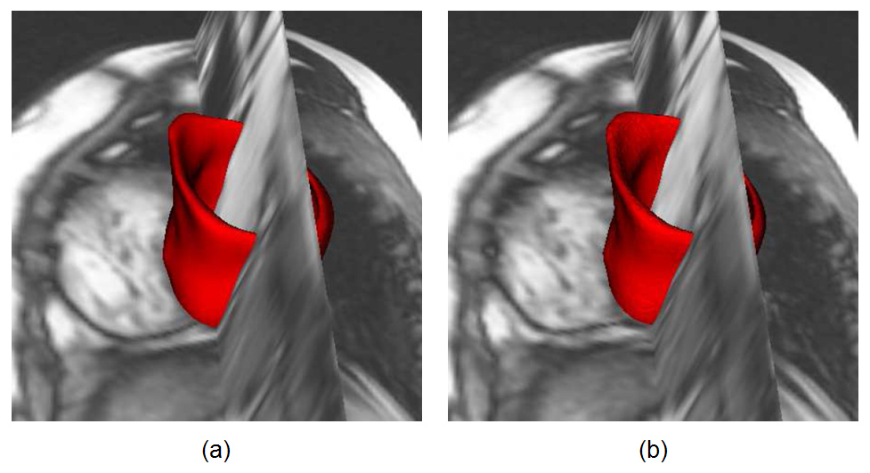
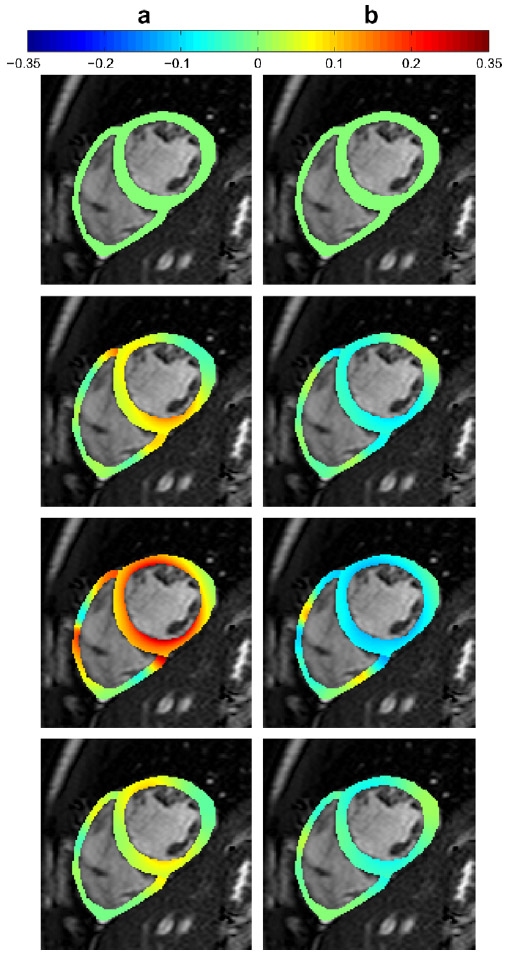
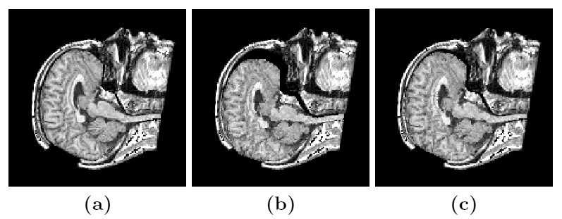
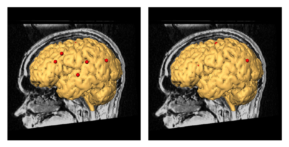
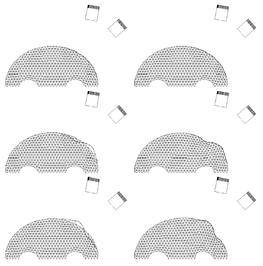
Figure 5: Interactive electrode strip manipulation. The user selected an electrode from the strip and interactively moved it in the direction perpendicular to the electrode disk until the strip assumed an improved shape. Electrodes can be interactively moved in tangent directions, too. As the user moved the electrode, the rest of the strip moved in a physically correct way. Then the user selected another electrode and repeated the process until the electrode strip was properly positioned. Note that the strip was not stretched or compressed during the manipulation, i.e. that the distances along the strip were preserved. The figure is from [3] and it is used with permission; Copyright © 2002 Oskar Skrinjar; All rights reserved.
References:
[1] Skrinjar, O., Duncan, J.: "Preserving Intrinsic Surface Distances - Application to Electrode Grid Manipulation", IEEE Workshop on Mathematical Methods in Biomedical Image Analysis, Hilton Head Island, SC, USA, pp. 54-60, June 2000. LINK
[2] Skrinjar, O., Duncan, J., "Automatic Extraction of Implanted Electrode Grids", Medical Image Computing and Computer Assisted Intervention, Proceedings, Cambridge, UK, pp. 990-997, September 1999. LINK
[3] Skrinjar, O., "Deformable Models in Image-Guided Neurosurgery", PhD Thesis, Yale University, May 2002. LINK